PID Servo
The Quarto can turn into a proportional-integral-differential (PID) Servo with just 20 lines of code! Let's see how.
Setup
The setup function is run once at start-up and is used to configure the ADC. For the servo, we want use ADC channel 1, so we use the function configureADC to configure it. We want the ADC to fire every 1µs and to have a voltage range of ±1.25V.
void setup(void) {
  configureADC(1,1,0,BIPOLAR_1250mV,getADC1); // Have ADC take measurement every 1us, ±1.25V range
}
With the Arduino 2.0 IDE, if we hover over the function configureADC, a window pops up showing the function arguments:
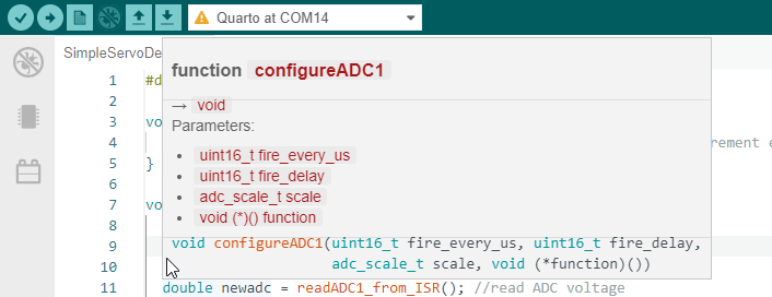
First argument, fire_every_us tells the ADC how often to fire. In this example, we want to run the ADC at its maximum rate of 1MSPS (1 Mega Samples Per Second) so we fire every 1us, so we set this parameter to one. If we wanted to sample every 5us (or 200 kHz sample rate), this should be set to 5.
The second argument, fire_delay delays when the ADC fires. This has no real meaning when only using one ADC channel, but if you configure multiple ADC channels, to control the timing relationship between different channels.
The next argument, scale sets the ADC voltage range. Valid inputs are BIPOLAR_1250mV BIPOLAR_2500mV, BIPOLAR_5V and BIPOLAR_10V. In this case, we want the ADC range to be ±1.25V, so we set it to BIPOLAR_1250mV .
Finally, the last argument, function is the function to call when there is ADC data. We will call this function getADC1 although the name does not matter.
We will also define a setpoint which is the target value we want to see at the ADC input. We will use a macro to do this so if we want to change the setpoint, we only have to change the value in one place. For this example, we will have the SETPOINT equal to 0.25
#define SETPOINT 0.25
Function when ADC Data is Available
We now need to define the function that is called when the ADC gets data. On our case this function is called getADC. Here's the code for that function:
void getADC1(void) {
  static double integral = 0;
  static double prev_adc = 0;

  double newadc = readADC1_from_ISR(); //read ADC voltage

  double prop = (newadc-SETPOINT) * 1.975; //proportional
  integral += (newadc - SETPOINT) * 0.01; // integral gain
  double diff = ( newadc - prev_adc) * 0.00001; // turn diff down for accuracate BW measurement
  double newdac = prop + integral + diff;

  writeDAC(1,-newdac); //invert for negative feedback. Write to DAC channel 1.
  prev_adc = newadc; //store new adc value for differential calculation
}
The first two lines of the function define two double-precision floating point numbers integral and prev_adc. These two definitions start with static which means that these variables do not disappear after the function runs, but they are kept for subsequent runs. So for the first run, integral and prev_adc start at 0. If at the end of the first run, integral is 1.2345, then integral will start with that value for the next run, and so on.
The next line reads the ADC1 value and stores it into the double newadc.
Any function that runs when new ADC data is available must execute the function readADCX_from_ISR()!
When the ADC has new data, it fires an interrupt. That interrupt executes the function configured in configureADCX and that function must clear the interrupt, which is done by running readADCX_from_ISR(). Otherwise the function will loop forever and the Quarto will crash.
The next set of commands calculate the proportional, integral and differential (PID) values. The proportional value is the difference between the ADC value (newadc) and the SETPOINT, multiplied by a scale constant, in this case 1.975. The integral calculation is similar, but with a different scale constant (0.01) and we use a += instead of an = to assign it a value so it sums the new calculation with the previous value of integral. Next, the differential looks at the difference between the current ADC value (newadc) and the previously measured ADC value (prev_adc) and multiplies that by the scale constant (0.00001). Finally, we sum these two values together in the new value newdac.
The second to last line of the function writes the newly calculated PID value to the channel 1 DAC using the writeDAC1 command. There is a minus sign in front of the argument newdac to invert the value, which we need to do to provide negative feedback.
The last line stores the most recent ADC measurement (newadc) in the variable prev_adc for use the next time this function is run.
Final Code
Putting this altogether, we have:
#define SETPOINT 0.25

void setup(void) {
  configureADC(1,1,0,BIPOLAR_1250mV,getADC1); // Have ADC take measurement every 1us, ±1.25V range
}

void getADC1(void) {
  static double integral = 0;
  static double prev_adc = 0;

  double newadc = readADC1_from_ISR(); //read ADC voltage

  double prop = (newadc-SETPOINT) * 1.975; //proportional
  integral += (newadc - SETPOINT) * 0.01; // integral gain
  double diff = ( newadc - prev_adc) * 0.00001; // turn diff down for accuracate BW measurement
  double newdac = prop + integral + diff;

  writeDAC(1,-newdac); //invert for negative feedback
  prev_adc = newadc; //store new adc value for differential calculation
}
Data
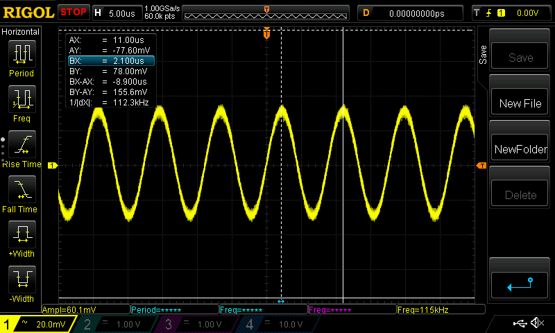
Using this code, if you connect the channel 1 DAC output to the ADC channel 1 input, the Quarto can lock to itself and it will oscillate at over 100 kHz, as shown below. (Just lower the proportional gain scalar from 1.975 to stop the oscillation)
Feature: Integrator Hold
What if you wanted your servo to support Integrator Hold (sometimes called Sample & Hold) where the servo output stays constant for a period of time, and then the servo re-engages lock later? We can implement this where a trigger line will control if the servo should be active or just holding its value. The first part is to define a variable servoActive that will store if the servo is active. Then we setup an interrupt to fire whenever trigger 1 changes its value and have it update the servoActive variable. We can do this with:
bool servoActive;

void setup(void) {
  triggerMode(1, INPUT); // Set trigger1 as input
  servoActive = triggerRead(1); //set servoActive variable initially based on trigger 1 level
  enableInterruptTrigger(1,BOTH_EDGES,&servo_en); //Run servo_en function on any change to trigger 1
  configureADC(1,1,0,BIPOLAR_1250mV,getADC1); // Have ADC take measurement every 1us, ±1.25V range
}

void servo_en(void) {
  servoActive = triggerRead(1);
}
Now all we have to do is wrap the servo functionality around an if statement that looks at the servoActive variable. Below is the complete code:
bool servoActive;

void setup(void) {
  triggerMode(1, INPUT); // Set trigger1 as input
  servoActive = triggerRead(1); //set servoActive variable initially based on trigger 1 level
  enableInterruptTrigger(1,BOTH_EDGES,&servo_en); //Run servo_en function on any change to trigger 1
  configureADC(1,1,0,BIPOLAR_1250mV,getADC1); // Have ADC take measurement every 1us, ±1.25V range
}


void servo_en(void) {
  servoActive = triggerRead(1);
}

void getADC1(void) {
  static double integral = 0;
  static double prev_adc = 0;
  double newadc = readADC1_from_ISR(); //read ADC voltage

  double setpoint = 0.25; // Target value for ADC to read

  if (servoActive) {
    double prop = (newadc - setpoint) * 1.975; //proportional
    integral += (newadc - setpoint) * 0.01; // integral gain
    double diff = ( newadc - prev_adc) * .00001; // turn diff down for accuracate BW measurement
    double newdac = prop + integral + diff;

    writeDAC(1,-newdac); //invert for negative feedback
  }
  prev_adc = newadc; //store new adc value for differential calculation
}


void loop(void) {
   static unsigned long lastrun = 0;

  if (millis() > lastrun) { //Run once every 1000ms
    lastrun = millis() + 1000;
    toggleLEDGreen();
    //Serial.println("This runs every second");
  }
}
This is one example of adding more functionality to the basic PID servo. The Quarto could be programmed to do double integration, or feed-forward, or compensate for temperature drift, or unlock-detection, or auto-locking, amout other features.