Measuring Interrupt Latency & Jitter
Overview
Whenever you want to micro-controller unit (MCU) to stop what it is doing to handle something else, an interrupt is needed to preempt the current task the MCU is executing. When new ADC data is ready, we use an interrupt to process that new data. Similarly when the USB has incoming data, an interrupt will fire so the MCU can switch to handling the new USB data. Interrupts enable a processor to juggle multiple tasks while still responding quickly to important events.
There are numerous reasons an processor will not respond as quickly to an interrupt as one would like. Many processors use instruction pipelining and caching, and these features reduce the processor's ability to quickly run different instructions. Also, processors usually have to spend time storing the working memory of their current task before they can respond to an interrupt. Additionally, some processors need to spend time determining which interrupt fired before the they can respond appropriately. And finally, the software the processor is running can limit the response time by, for example, disabling listening to any interrupts for a period of time.
In this application note, we will measure the time it takes for the Quarto to respond to an interrupt (often called the interrupt latency). In order to support quick response times and high servo bandwidth, the Quarto has been designed to have very low interrupt latency.
In this application note, we will assume that the interrupt we care about is running at the highest priority. If you have multiple interrupts firing then anything with a lower priority will be delayed until the higher priority interrupt finishes. In such a situation, the interrupt latency becomes much more complex for low-priority interrupts.
Trigger Interrupt Latency
In this example, we will measure the interrupt latency from an external trigger, although the data would look the same for new ADC data as well. Here is basic code for configuring an interrupt to execute the function gotTrigger on the rising edge of Trigger 1.
void setup() {
  triggerMode(2,OUTPUT); // Use Trigger 2 as output
  enableInterruptTrigger(1,RISING_EDGE, gotTrigger); // Run gotTrigger on Trigger 1 rising edge
}

void gotTrigger(void) {
  triggerWrite(2,HIGH); // Set Trigger 2 to go high so when know when function begins to run
  delayNanoseconds(100); // Function runs too fast to see Trigger 2 pulse on O-scope otherwise
  triggerWrite(2,LOW); // Set Trigger 2 go to low when function completes
}
An oscilloscope is configured to display with 10s of persistence so we can see multiple trigger responses on the same screen. The cyan trace shows the Trigger 1 input and yellow shows Trigger 2.
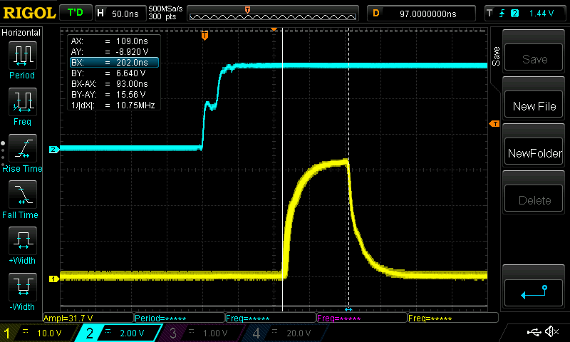
The Trigger 2 goes high about 110ns after the Trigger 1 goes high. So the Interrupt Latency is approximately 110ns. The gotTrigger() function finishes executing about 90ns later. Because of the persistence setup on the oscilloscope, the yellow trace is broadened by the timing jitter, as sometimes the response is a little faster or slower. But this is on the order of only 10ns.
While 110ns latency is terrific, this is under ideal circumstances as we will see in the next section.
Latency Under Load
The previous code generated a nice baseline, however, the MCU was never doing anything except handling the Trigger 1 interrupt, so it was in an ideal position to respond quickly. Realistically, the MCU will be busy handling USB data and doing other tasks in the main loop. This will add jitter to the latency as sometimes the MCU is idle and sometimes it has to store what it is working on to memory before it can respond to the interrupt. To model this better, we've added a new loop function that the MCU continuously runs. In the loop, we will do a few things:
- USB: echo back any USB data that is received
- Math: Do a math calculation all the time in the loop function
- LED: Toggle the front panel LED every 500ms
The new code is:
void setup() {
  triggerMode(2,OUTPUT); // Use Trigger 2 as output
  enableInterruptTrigger(1,RISING_EDGE, gotTrigger); // Run gotTrigger on Trigger 1 rising edge
}

void gotTrigger(void) {
  triggerWrite(2,HIGH); // Set Trigger 2 to go high so when know when function begins to run
  delayNanoseconds(100); // Function runs too fast to see Trigger 2 pulse on O-scope otherwise
  triggerWrite(2,LOW); // Set Trigger 2 go to low when function completes
}

void loop() {
  static unsigned long lastrun;
  static signed long total;

  if (millis() > lastrun + 500) { //Run once every 500ms
    toggleLEDGreen(); //toggle green LED;
    lastrun = lastrun + 500;
  }

  total += 324*(total-2343); //do some math in main loop

  char dat;
  while (Serial.available() > 0) {
    dat = Serial.read(); //Read USB data if available
    Serial.print(dat); //Echo data back over USB
  }
}
An external function generator was used to have Trigger 1 go from low to high once every 1μs (frequency of 1 MHz) and a python script was used to stream data in and out of the Quarto (18 Mbps down, 18 Mbps up). While all this was happening , let's look at the response time again with the oscilloscope still set at 10s persistence:
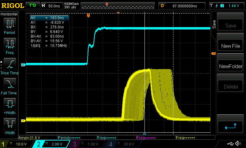
The response it still usually about 110ns, however, over the 10s oscilloscope window, we can see there are numerous events where the latency is higher. Especially when using the Quarto for servoing, the consistency of the response time is just as important as the response time is itself. In the worst case, Trigger 2 falls 275ns after the rising edge of Trigger 1. That 275ns includes the interrupt latency, the function execution time and the maximum timing jitter. With the minimal latency of 110ns and the function taking 90ns to run, the jitter is the remainder: 275ns - 110ns - 90ns = 75ns. So the interrupt latency varies between 110ns and 185ns.
Worst-Case Latency
There is another limitation on the latency that we haven't mentioned: getting data into and out of the floating point unit (FPU). If the main process is doing floating point math (using floats or doubles in C), then it is using the FPU. If an interrupt fires that also needs to do floating point math, then, just like the MCU, the FPU needs to clean up and store what it is working on before it can process the new data. This adds additional jitter to the interrupt latency we measured previously. To test this, we will take our previous code but have both the main loop and the trigger interrupt do math on double precision floats. The new code is below.
void setup() {
  triggerMode(2,OUTPUT); // Use Trigger 2 as output
  enableInterruptTrigger(1,true, gotTrigger); // Run gotTrigger on Trigger 1 rising edge
}
double DACout = 0; //global variable used by main loop and gotTrigger

void gotTrigger(void) {
  triggerWrite(2,HIGH); // Set Trigger 2 to go high so when know when function begins to run
  writeDAC1(DACout*(DACout*2.342-3.232)); //Do some floating point math and then update the DAC with the result
  delayNanoseconds(100); // Function runs too fast to see Trigger 2 pulse on O-scope otherwise
  triggerWrite(2,LOW); // Set Trigger 2 to go low when function completes
}

void loop() {
  static unsigned long lastrun;
  static signed long total;

  if (millis() > lastrun + 500) { //Run once every 500ms
    toggleLEDGreen(); //toggle green LED;
    lastrun = lastrun + 500;
  }

  DACout += 3.2342*sin(DACout*23.234+65.324); //do some FPU math in main loop

  char dat;
  while (Serial.available() > 0) {
    dat = Serial.read(); //Read USB data if available
    Serial.print(dat); //Echo data back over USB
  }
}
In summary, the Quarto is doing the following:
- Every 1μs, handle external trigger, do floating point math and update the DAC
- Do floating point math in main loop all the time
- Receive USB data at 15 Mbps
- Transmit USB data at 15 Mbps
In this setup, we get the following latency measurement:
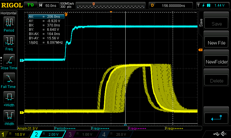
The interrupt latency is now rarely at 110ns, but usually closer to 125ns. However, the worst case latency is 210ns. So the interrupt latency varies between 110ns and 210ns and the maximum jitter is now 100ns (before it was 75ns). Additionally, the gotTrigger function now takes 160ns as it is doing math and updating the DAC in addition to the 100ns delay we programmed in. The gotTrigger function sometimes finishes as late as 370ns after the trigger fired, which is consistent with 110ns latency + 100 ns jitter + 160ns execution time. Even when pushing the Quarto to its limits, the interrupt latency is bounded to be under about 210ns.
For a 100 kHz PID Servo, the total loop delay is 5us (180° phase shift at 100kHz), so 100ns of timing jitter is only 2% timing variation, a small effect. Having consistent and bounded interrupt latency is crucial for consistent loop bandwidths and response times.
Footnotes
To generate the data presented above, the following python script was used to stream data to and from the Quarto:
import serial,time,os
ser = serial.Serial('COM4')
packets = 400
loops = 200
packetSizeSend = 64*64
packetSizeReceive = packetSizeSend

loop=0
for empty in range(loops):
    loop = loop + 1
    start=time.time()
    for i in range(packets):
        byte = os.urandom(packetSizeSend)
        ser.write(byte)
        data=ser.read(packetSizeReceive)

        if byte != data:
            print('Error: Return data does not match. Length = {} and {}'.format(len(byte),len(data)))

    stop=time.time()
    rescaleSend = 8*packetSizeSend*packets/1000000.0/max(.000001,(stop-start))
    rescaleReceive = 8*packetSizeReceive*packets/1000000.0/max(.000001,(stop-start))
    print('Send Rate: {:0.2f} MBaud, Receive Rate: {:0.2f} MBaud. Got {} kBytes and received {} kBytes in {:0.2f} ms (Loop {}/{})'.format(rescaleSend,rescaleReceive,packets*packetSizeSend/1000,packets*packetSizeReceive/1000,(stop-start)*1000,loop,loops))
del ser
Running the script with the Quarto running the code from the Worst-Case Latency section outputs:
...
Send Rate: 15.79 MBaud, Receive Rate: 15.79 MBaud. Got 1638.4 kBytes and received 1638.4 kBytes in 830.08 ms (Loop 196/200)
Send Rate: 15.56 MBaud, Receive Rate: 15.56 MBaud. Got 1638.4 kBytes and received 1638.4 kBytes in 842.31 ms (Loop 197/200)
Send Rate: 15.46 MBaud, Receive Rate: 15.46 MBaud. Got 1638.4 kBytes and received 1638.4 kBytes in 847.92 ms (Loop 198/200)
Send Rate: 15.68 MBaud, Receive Rate: 15.68 MBaud. Got 1638.4 kBytes and received 1638.4 kBytes in 835.76 ms (Loop 199/200)
Send Rate: 15.67 MBaud, Receive Rate: 15.67 MBaud. Got 1638.4 kBytes and received 1638.4 kBytes in 836.39 ms (Loop 200/200)