Lock-in Amplifier
This example will show how to use the Quarto as a lock-in amplifier.
Generate Reference
We will use the ADC sampling rate as the 'heartbeat' to control the timing of the full system. The first step is to configure ADC channel 1 to collect data every 2µs with a voltage range of ±10V (see PID Servo for more details on this setup). The function getADC1 will run when there is new ADC data (every 2µs) and in that function we will update DAC channel 1 to generate a sine-wave output.
const uint SampleRate = 2;
double frequency = 10e3;
double amplitude = 5.0;

void setup(void) {
  configureADC(1,SampleRate,0,BIPOLAR_10V,getADC1); // Have ADC take measurement every 2us, ±10V range
}

void getADC1(void) {
  static double cycle = 0; //track phase/(2*pi) which is cycle fraction (one cycle=2pi).
  double newadc = readADC1_from_ISR(); //read ADC voltage
  cycle += frequency / (1e6/SampleRate); //1e6/SampleRate is sample freq (500kHz);  freq normed to that

  writeDAC(1,amplitude*sin(2*PI*cycle)); //DAC output is sin(2*pi*cycle)
  if (cycle > 1) cycle -= 1; //reset phase so no overflows
}
Everytime the ADC gets a new datapoint, we increment the phase and take the sine of that phase to get the desired DAC output. Mathematically we track instead of phase so the phase-resets do not have rounding errors from the .
Demodulate
At the heart of a lock-in amplifier is a multiplier. By multiplying the input signal by the reference signal, the component of the input signal at the reference frequency gets moved to DC, where it can be measured more directly. In analog circuits, this is done with a mixer, but with Quarto we can just multiply the digitized signals:
double multiplied = newadc * sin(2*PI*cycle);
We can then output that new signal on Analog Output #2 (DAC2):
const uint SampleRate = 2;
double frequency = 10e3;
double phase = 0;
double amplitude = 5.0;

void setup(void) {
  configureADC(1,SampleRate,0,BIPOLAR_10V,getADC1); // Have ADC take measurement every 2us, ±10V range
}

void getADC1(void) {
  static double cycle = 0; //track phase/(2*pi) which is cycle fraction (one cycle=2pi).
  double newadc = readADC1_from_ISR(); //read ADC voltage
  cycle += frequency / (1e6/SampleRate); //1e6/SampleRate is sample freq (500kHz); freq normed to that

  writeDAC(1,amplitude*sin(2*PI*cycle)); //DAC output is sin(2*pi*cycle)
  double multiplied = newadc * sin(2*PI*(cycle + phase/360));
  writeDAC(2,multiplied);
  if (cycle > 1) cycle -= 1; //reset phase so no overflows
}
Speed Optimization
While it does not matter much in this demo, if using the DAC2 output as part of a servo loop, decreasing the latency on the DAC update may be important. Let's look at the sequence of events that happens inside the getADC1 function:
- New ADC data comes in
- Update cycle count
- Calculate sine of new cycle count
- Update DAC1 with sine result
- Calculate sine of cycle count plus phase shift
- Update DAC2 with sine result times ADC data
Calculating the sine is a relatively slow calculation that can often take ~600ns (the time varies based on the input value) so doing two of those calculations will add some delay to the sequence. However, neigher sine calculation uses the ADC data as an argument. This means that we know ahead of time what sine calculations we will need, so we can precalcuate them. This enables us to re-order the calcuation such that the DAC2 update is earlier in the process:
- New ADC data comes in
- Update DAC1 with stored sine result
- Update DAC2 with other stored sine times ADC data
- Update cycle count
- Calculate sine of new cycle count and store
- Calculate sine of new cycle count plus phase shift and store
All we have done is reorder the operations, but now the delay in changes so the DAC2 output is set only by steps 1 - 3, instead of steps 1 - 6. Here's the updated function getADC1 :
void getADC1(void) {
  static double nextSin = 0;
  static double nextSinWithPhase = 0;
  static double cycle = 0; //track phase/(2*pi) which is cycle fraction (one cycle=2pi).

  double newadc = readADC1_from_ISR(); //read ADC voltage
  writeDAC(1,amplitude*nextSin); //DAC output is sin(2*pi*cycle)
  double multiplied = newadc * nextSinWithPhase; //put phase in units if degrees
  writeDAC(2,multiplied);

  cycle += frequency / (1e6/SampleRate); //1e6/SampleRate is sample freq (500kHz);  freq normed to that
  if (cycle > 1) cycle -= 1; //reset phase so no overflows
  nextSin = sin(2*PI*cycle);
  nextSinWithPhase = sin(2*PI*(cycle + phase/360));
}
This optimization decreases the latency of the Quarto, but does not change how much time is spent processing the data. If you wanted to do that, one technique would be to set the output frequency to be the ADC rate (or a low multiple of it) divided by an integer. This would make the sine calculations periodic and they could all be calculated once ahead of time and then getADC1 could just lookup the right value. The approach shown here however yields good latency and lets the frequency be set arbitrarily.
Data
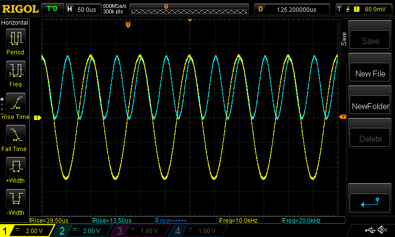
If you connect the Analog Output #1 to the Analog Input #1 input, then the output on Analog Ouput #2 will be a sine wave at twice the frequency and half the amplitude and a DC offset equal to half the amplitude. This is because of the trig identity:
The image below shows the Analog Input #1 sine wave (yellow trace) and the multiplied Analog Output #2 (cyan trace):
Adjustable Parameters
In the above example, the output sine wave was fixed at an amplitude of 5V, a frequency of 10 kHz, and the phase shift between the output frequency and the demodulation was also fixed at 0°. We will use the qCommand library to use Serial commands to adjust these parameters (see Serial Commands for more details). The new code is:
#include "qCommand.h"
qCommand qC;
const uint SampleRate = 2;
double frequency = 10e3;
double phase = 0;
double amplitude = 5;
void setup(void) {
configureADC(1,SampleRate,0,BIPOLAR_10V,getADC1); // Have ADC take measurement every 2us, ±10V range
qC.assignVariable("Freq",&frequency);
qC.assignVariable("Phase",&phase);
qC.assignVariable("Amp",&litude);
}
void loop(void) {
qC.readSerial(Serial);
qC.readSerial(Serial2);
}
void getADC1(void) {
static double nextSin = 0;
static double nextSinWithPhase = 0;
static double cycle = 0; //track phase/(2*pi) which is cycle fraction (one cycle=2pi).
double newadc = readADC1_from_ISR(); //read ADC voltage
writeDAC(1,amplitude*nextSin); //DAC output is sin(2*pi*cycle)
double multiplied = newadc * nextSinWithPhase; //put phase in units if degrees
writeDAC(2,multiplied);
cycle += frequency / (1e6/SampleRate); //1e6/SampleRate is sample freq (500kHz); freq normed to that
if (cycle > 1) cycle -= 1; //reset phase so no overflows
nextSin = sin(2*PI*cycle);
nextSinWithPhase = sin(2*PI*(cycle + phase/360));
}
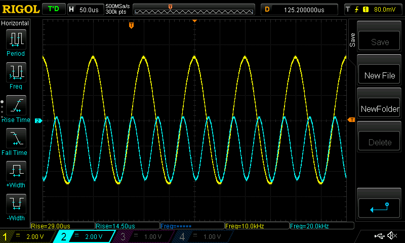
Now we can adjust the phase (and frequency and amplitude) over the serial port:
>>phase 180
<< phase is 1.8000000e+02
And when we do that, our trig equation becomes
The same setup on an O-scope now looks like:
Filtering
Often however, the oscillation at twice the reference frequency (2f) isn't desired and we want to filter it out. We will use the simple first-order IIR filter described in more detail in Digital Filter section of the Analog Filter Example. To set the cut-off frequency to will use a custom qCommand function so we can input a frequency in Hz and calculate that right value of for the filter. Here's the code:
#include "qCommand.h"
qCommand qC;
const uint SampleRate = 2;
double frequency = 10e3;
double phase = 0;
double amplitude = 5;
double filter = 1e3; //default 1kHz
double alpha = 0.012488; // alpha for default 1 kHz
double output = 0;
void setup(void) {
configureADC(1,SampleRate,0,BIPOLAR_10V,getADC1); // Have ADC take measurement every 2us, ±10V range
qC.assignVariable("Freq",&frequency);
qC.assignVariable("Phase",&phase);
qC.assignVariable("Amp",&litude);
qC.assignVariable("Output",&output);
qC.addCommand("Filter",&adjFilter);
}
void loop(void) {
qC.readSerial(Serial);
qC.readSerial(Serial2);
}
void getADC1(void) {
static double nextSin = 0;
static double nextSinWithPhase = 0;
static double cycle = 0; //track phase/(2*pi) which is cycle fraction (one cycle=2pi).
double newadc = readADC1_from_ISR(); //read ADC voltage
writeDAC(1,amplitude*nextSin); //DAC output is sin(2*pi*cycle)
double multiplied = newadc * nextSinWithPhase; //put phase in units if degrees
output = alpha * multiplied + (1-alpha) * output; //apply IIR filter on multiplied value
writeDAC(2,output);
cycle += frequency / (1e6/SampleRate); //1e6/SampleRate is sample freq (500kHz); freq normed to that
if (cycle > 1) cycle -= 1; //reset phase so no overflows
nextSin = sin(2*PI*cycle);
nextSinWithPhase = sin(2*PI*(cycle + phase/360));
}
void adjFilter(qCommand& qC, Stream& S) {
if ( qC.next() != NULL) {
double filterInput = atof(qC.current());
if (filterInput < 0 ) {
filter = 0; //keep frequency filter positive
alpha = 0; //at filter = 0Hz, output cannot update, alpha is zero
} else if (filterInput > 250e3/SampleRate) { // IIR no valid beyond sampleRate/4
filter = INFINITY;
alpha = 1; //no filtering
} else {
filter = filterInput;
double y = tan(PI * filter * SampleRate * 1e-6);
alpha = 2 * y / (y+1);
}
}
S.printf("The filter frequency is %f (and alpha=%f)\n",filter,alpha);
}
Now we can adjust the filtering on the fly:
>> filter 20e3
<< The filter frequency is 20000.000000 (and alpha=0.224320)
>> filter 1e3
<< The filter frequency is 1000.000000 (and alpha=0.012488)
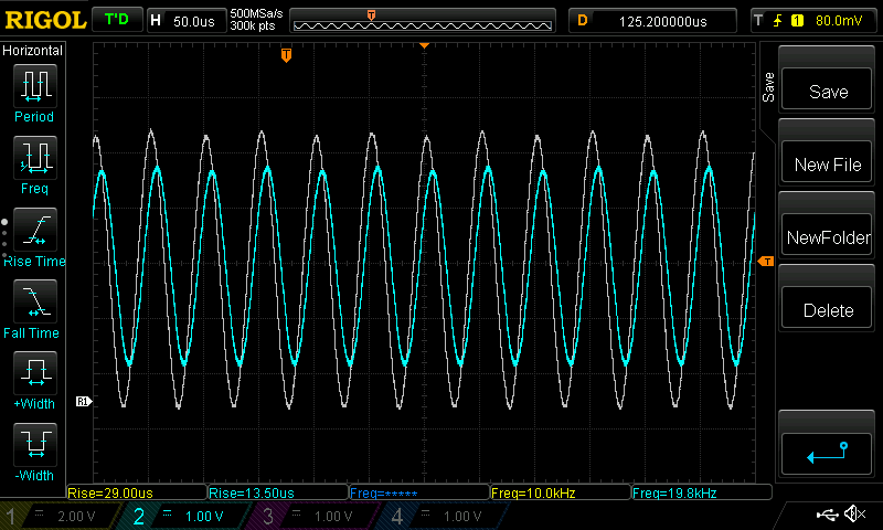
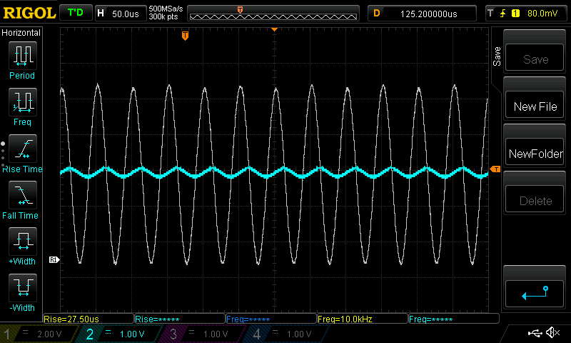
Below are two O-scope screen shots showing the filtered output in cyan with a reference grey trace showing the results without any filtering. The first image shows a 20 kHz filter, causing the amplitude of the 2f frequency component to be reduced by . The second image is with a filter of 1kHz where the 2f component is reduced by ~20.
Using the Lock-in
With this setup, we can actually measure the phase-delay caused by the Quarto. If the Quarto had zero signal delay (infinite bandwidth), then the output signal would be maximized with a phase shift of 0° and, conversely the output would be zero with a phase shift of 90°. But the process reading, writing and filtering analog data takes some time, causing a phase shift relative to the expected value. By adjusting the phase we can compensate for this shift and measure the phase shift caused by the Quarto.
The first step is to setup an agressive filter so we can precisely measure the output voltage. It is easier to measure when a signal is at 0V than when it is maximized, so we will look for the phase necessary to get zero output (ideal is 90°). Also, we will use the command 'Output' to measure the output voltage directly from the Quarto.
>> filter 10
<< The filter frequency is 10.000000 (and alpha=0.000126)
>> phase 90
>> phase is 9.000000e+01
<< output
>> output is -0.767086
>> output is -0.768395
>> output is -0.767349
>> output is -0.767659
>> output is -0.766547
>> output is -0.766430
>> output is -0.768701
>> output is -0.766498
>> output is -0.766945
We can see that with a 90° phase shift, the output is -0.767V with a standard deviation of about 800uV, which should be low enough make a precise measurement. If we change the phase, we can see the output change:
>> phase 95
<< phase is 9.500000e+01
>> output
<< output is -0.970563
>> phase 85
<< phase is 8.500000e+01
>> output
<< output is -0.559031
Experimentally, the zero crossing was found around 72.1°:
>> phase 72.1
<< phase is 7.210000e+01
>> output
<< output is -8.996903e-04
<< output is 1.919594e-04
<< output is -2.021857e-03
This is a phase shift of about 18° from the expected 90°. See Analog Response Time for more details, but this is expected since the Quarto has 100 kHz of servo bandwidth when sampling at 2µs. That works out to 180° phase shift at 100 kHz, which would be an 18° phase-shift at 10 kHz.