Analog Filter with Gain and Subtraction
The Quarto can be used to filter analog signals. In this example, we will take two analog inputs, , and and create a new output defined by the following equation:
Finally, we will low-pass filter this signal with a cut-off frequency of 10 kHz. We will output the unfiltered signal on DAC channel 1 and the filtered signal on DAC channel 2.
Setup
In this example, we will fully utilize the 1 mega-sample per second (MSPS) capability of the Quarto and have it measure two analog channels at 500 kHz each. This means each channel will make a measurement every 2μs. That is configured in the setup function:
double analog_output = 0;
double adc1 = 0;

void setup() {
  configureADC(1,2,0,BIPOLAR_5V,getADC1); // Have ADC1 take measurement every 2us, ±5V range
  configureADC(2,2,1,BIPOLAR_5V,getADC2); // Have ADC2 take measurement every 2us, ±5V range
}
In this case, both ADC channels are set to the ±5V range. Additionally, we defined two global variables, analog_output and adc1 for future use.
Main Functions
When ADC1 gets its measurement, we need to wait until ADC2 gets its measurement as well before we can proceed, so we will just store the result. Then when ADC2 gets its measurement, we can do the subtraction and amplification. So the two callback functions getADC1 and getADC2 that we configured in the setup will become:
void getADC1() {
  adc1 = readADC1_from_ISR(); //store ADC1 voltage measurement
}

void getADC2() {
  double adc2 = readADC2_from_ISR(); //store ADC2 voltage measurement
  double pre_filter = (adc1 - adc2 * 1.05 ) * 3.75;
  writeDAC(1,pre_filter); //write value to DAC1
}
Now we have implemented as defined above by doing a weighted subtraction between ADC channel 1 and channel 2 and then multipling the result by 3.75. The next step is to apply the low-pass filter to this result.
The Digital Filter
Digital filtering is a complex topic, and this example is only going to give an intuitive explanation and will not go into the theory. For reference, the filter we are implementing is a first-order infinite impulse filter (IIR) and we will use it to approximate a first-order analog R-C filter.
To low-pass filter the signal, we want to stop it from changing too quickly, and to do this we want to limit how much a new ADC measurement can affect the output. The simplest way to do this is have:
where is between 0 (exclusive) and 1. The smaller is, the less influenced the Output is by the Input. The problem with this is that while the Output is less influenced from fast changes in the Input, it is also less influenced by all changes from the Input, regardless of the frequency of that change. We want a unity filter where for slow signals, the Output equals the Input, so we need to add back the low-frequency gain Output lost from the attenuation caused by . We will add this gain back by adding a term that anchors the Output to its previous value, Outputprevious.
Now when the Input suddenly changes, the Output will only change by an amout set by the factor . That increase, however, will cause the Outputprevious to increase, which will then cause Output to increase. Which will cause Outputprevious to increase. Which will cause Output to increase, and so on and so on. To determine the final (or steady-state) value of Output, we set Output = Outputprevious since Output is no longer changing. Then the above equation becomes
And we see that the Output equals the Input. The coefficient determins how fast the Output gets to the Input value. A low means it takes along time for Output to change from a change in the Input, while an near 1 would cause Output to very quickly match any change in the Input. This filter is a good approximation of an analog low-pass R-C filter. Now that we have the basic filter, we can implement it by adding just a single line to our getADC2 function:
void getADC2() {
  double adc2 = readADC2_from_ISR(); //store ADC2 voltage measurement
  double pre_filter = (adc1 - adc2 * 1.05 ) * 3.75;
  analog_output = a * pre_filter + (1-a) * analog_output;
  writeDAC(1,pre_filter); //write value to DAC1
  writeDAC(2,analog_output); //write value to DAC2
}
where a is a constant between 0 and 1 that we need to define.
Setting α
We won't cover the derivation here. But for the filter implemented above, the following equations can be used to relate the value of to the filter cut-off frequency () and the sampling interval ():
In this example, , . So and .
Final Code
Putting this altogether (and code to have the frontpanel LED blink every second), we have:
double analog_output = 0;
double adc1 = 0;
double a = 0.11838; // 10kHz filter

void setup() {
  configureADC(1,2,0,BIPOLAR_5V,getADC1); // Have ADC take measurement every 2us, ±5V range
  configureADC(2,2,1,BIPOLAR_5V,getADC2); // Have ADC take measurement every 2us, ±5V range
}

void getADC1() {
  adc1 = readADC1_from_ISR(); //store ADC1 voltage measurement
}

void getADC2() {
  double adc2 = readADC2_from_ISR(); //store ADC2 voltage measurement
  double pre_filter = (adc1 - adc2 * 1.05 ) * 3.75;
  analog_output = a * pre_filter + (1-a) * analog_output;
  writeDAC(1,pre_filter); //write unfiltered value to DAC1
  writeDAC(2,analog_output); //write filtered value to DAC2
}

void loop() {
  static uint lastrun1;
  if (millis() > lastrun1 + 500) {
      lastrun1 = millis();
      toggleLEDGreen();
  }
}
Data
Using this code, if we send a triangle wave into ADC 1 (yellow) and a square wave into ADC 2 (cyan), then we get the following output:
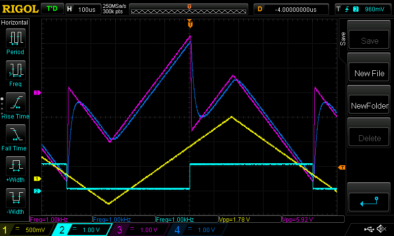
where DAC 1 is the unfiltered DAC 1 output (magenta) and DAC 2 has the filtered output (blue).